 HutchBook.com
W. L. Roorbach & G. W. Tucker Bottle Stopper
William L. Roorbach and George W.
Tucker's patent
application was filed October 14, 1889 (renewed May 6, 1890) and
specified:
We, WILLIAM L. ROORBACH and GEORGE W. TUCKER, both citizens of the United States, and residents of Philadelphia, Pennsylvania, have invented certain improvements in Bottle-Stoppers, of which the following is a specification.
Our invention relates to that class of bottle-stoppers known as "internal stoppers," the object of our invention being to so construct the stopper that it will be light and float upon the liquid in the bottle during the process of filling, and that it will quickly seat itself as soon as the filling-tube is removed.
A further object of our invention is to provide a bottle-stopper that can be used with an upright filling-machine now in common use in bottling with the common cork and wire bail...
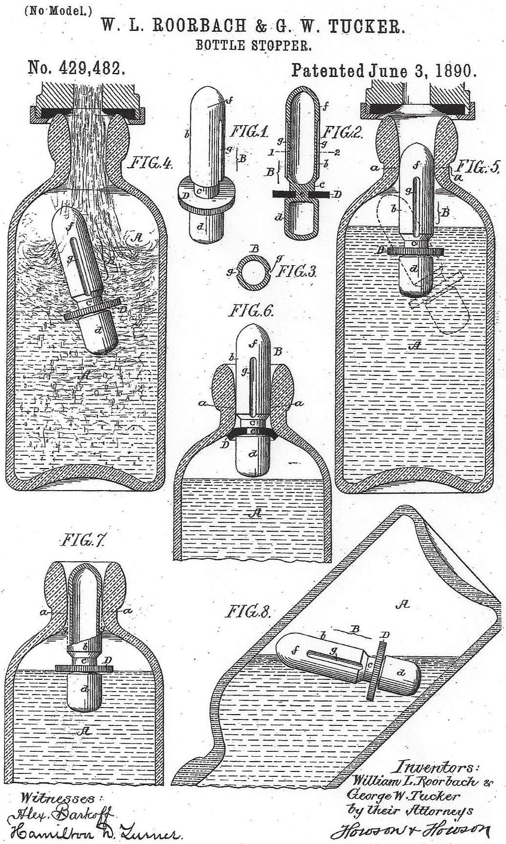
A is the bottle, having a neck of the form show, the portion a of the neck being of a certain size to correspond with a certain size of stopper.
B is the stopper, having an oblong portion b, which is cylindrical in form and hollow, as shown in Fig. 2. This portion b is reduced at c for a purpose described hereinafter.
Connected to the portion b by a neck e is a portion d of the form shown in Fig. 2. This portion is also made hollow.
Around the neck is a washer or sealing-disk D, made preferably of flexible rubber.
In order to make the stopper as light as possible, we make it out of vulcanized rubber, it being very light and buoyant, floating upon the surface of the liquid in the bottle during the process of filling and emptying, as clearly shown in the diagrams, Figs. 4 to 8. The portion f of the stopper is of a size to snugly pass through the neck of the bottle at the point a, and commencing directly under this portion f of the stopper are two or more longitudinal grooves g, extending to the cutaway space c, although in some instances one groove may be used. The object of this cutaway space c is that when the stopper is forced into the bottle in the first place the sealing-disk will be turned into this space and allow the stopper to pass through the neck...portion f acts as a plunger for the stopper during the filling of the bottle, so as to insure the proper seating of the sealing-disk.
We will now explain the operation of filling the bottle: As shown in Fig. 4, the nipple of the ordinary bottle-filling machine is placed in position on the head of the bottle, and the liquid with the gas is turned into the bottle. The force of this liquid and gas tends to right the stopper, as shown clearly in Fig. 4, the stopper being prevented from reversing, owing to the fact that it is longer than the bottle is wide. When the bottle is filled and the flow of liquid and gas cut off, the stopper floats partly immersed in the liquid, as shown by the dotted lines in Fig. 5, and remains in this position until the nipple of the filling-machine has been removed, and as soon as this nipple is removed, the stopper is forced out of the liquid into the mouth of the bottle, as shown by full lines in Fig. 5, the head f of the stopper fitting snugly but sliding freely through the portion A of the neck, thus preventing for a moment the escape of liquid or gas past the stopper. The pressure, however, continues, and immediately the stopper is forced from the position shown in Fig 5 to that shown in Fig. 6, sealing the bottle...This action...is instantaneous...owing to its peculiar shape and buoyancy...the percentage of breakage in the filling of a bottle with our improved stopper is small in comparison to the breakage in filling bottles by the method usually employed.
When it is wished to empty the bottles of the contents, the stopper is depressed, as shown in Fig. 7, so that the gas can escape around the sealing-disk through the grooves in the stopper and around the head until sufficient gas escapes to allow the stopper to fall from the mouth of the bottle to the surface of the liquid contained therein. At the same time the bottle is turned as shown in Fig. 8, in order to pour the contents out, and the stopper being buoyant will float on the surface of the liquid clear of the mouth of the bottle, not obstructing the mouth in any way. The objection to a light stopper of this class is that upon opening the bottle the stopper will be forced back to its seat by the pressure of gas within the bottle, there being no way for the gas to escape quickly; but by having the stopper grooved, as above mentioned, this objection is entirely overcome.
Another advantage of our improved stopper is that the bottle can be readily cleaned by the usual brush mechanism now used in cleaning bottles with detachable or exterior stoppers, the mechanism cleaning the stopper at the same time that it cleans the bottle.
The stopper can be removed from the bottle by first removing the sealing-disk from the stem; but this is not necessary, as the stopper after once inserted into the bottle need never be removed therefrom.
We prefer to make the stopper of vulcanized rubber, as it is comparatively light, strong, and has an even surface. The stoppers can be blown in molds, so that they will be exactly alike.
Comments:
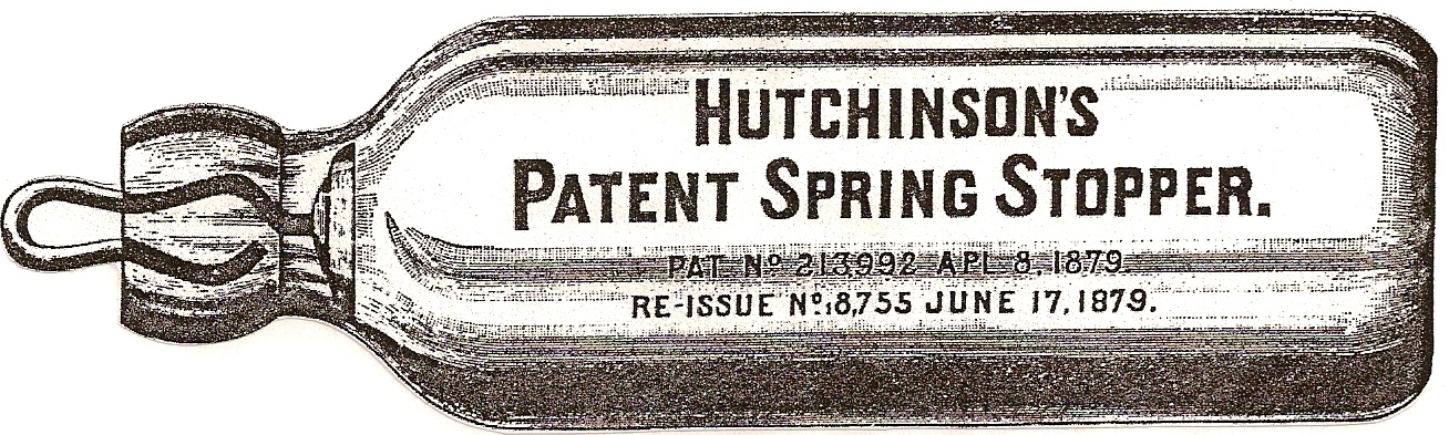
This is another bottle-stopper patent that sounded like a winner on paper, but wasn't a commercial success with bottlers and/or customers. Roorbach and Tucker obviously designed this closure to be used as a replacement for Hutchinson's Patent Spring Stoppers, evidence the images of bottles accompanying their patent filing were clearly designed for use with Hutchinson stoppers.